You are hereHome / Arduino Projects / Project Page: Hood Hoodie
Project Page: Hood Hoodie
A Hoodie for all Hoods
It’s one thing to have the name of the state that you live in or your home town emblazoned on your chest, but how about a piece of smart clothing that adjusts to where it is? I live in a city where over 77,000 people are crammed into 4.2 square miles. If I walk a mile from my apartment I will cross the boundaries of three distinct neighborhoods. The Hood Hoodie lets me proudly display the name of the neighborhood that I am standing in, wherever I am.
Mapping Neighborhoods
When I began to design the Hood Hoodie I thought that the most difficult part would be determining which neighborhood I am in based on raw GPS data. This turned out to be pretty easy once neighborhood boundaries were defined, using the point-in-polygon algorithm.
Defining the neighborhood boundaries proved to be more of a challenge than I anticipated. In these times when one can download close to any data imaginable my belief was that I would be only a few clicks away from a set of data points I could plug into my code. I only found one source of neighborhood data, from a real estate company. For reasons I don’t really remember this source did not work out for me. I had to build my data from scratch. The two tasks before me were to identify each neighborhood in the city and then build polygons around them.

When I think of on-line maps I think of Google. Unfortunately, they did not have, or at least I could not find, tools for drawing polygons on a map. I found a tool at Bing, of all places. The Google maps had neighborhoods better marked. I had to eyeball the neighborhoods on Google and draw them out in Bing. The coordinates were extracted with some laborious copying and pasting. It was not a very streamlined process, but it worked.
The Tech
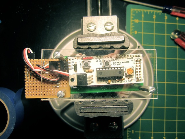
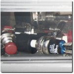
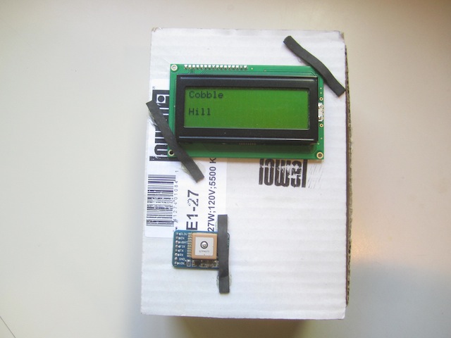
GPS data is read by an Adafruit Ultimate GPS module and processed by a Modern Device RBBB. I choose to use a serial backpack, made by Modern Device, for the LCD to simplify wiring. One thing about a GPS project is that you have to field test it right away. Sitting around in your house looking at the same latitude and longitude reading is not going to tell you much. I packed the hardware into a cardboard box and took a walk around the block. The coordinates changed and were reported correctly, the first test was a success. The next step was to write the neighborhood recognition code.
To test this code I plugged in some coordinates that were in different neighborhoods as well as some that were outside all neighborhoods. All was good, but of course I had to hit the pavement for a real test. As I loaded in more neighborhood data the program began to display the erratic behavior of one that is out of memory. It was clear that I had to store neighborhood data externally, so I added storage on SD card. Each neighborhood is represented by a string of characters and a series of line segments that make up the polygon around it. A line segment has two latitude, longitude pairs stored as two floats. With up to 20 line segments per neighborhood the storage required adds up quickly. In terms of performance, reading several neighborhoods off SD card every time new
GPS data is processed is expensive. To be more efficient the neighborhood name and it bounding box are stored in memory. When processing coordinates the code considers each bounding box to determine whether they might be in a neighborhood. If so then the full neighborhood definition is read from the SD card and the point-in-polygon algorithm is applied to the coordinates. As soon as coordinates are found to be in a neighborhood its name is displayed on the LCD. If no match is found the latitude and longitude are displayed.
The Textile

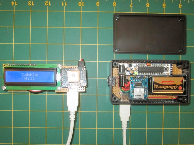
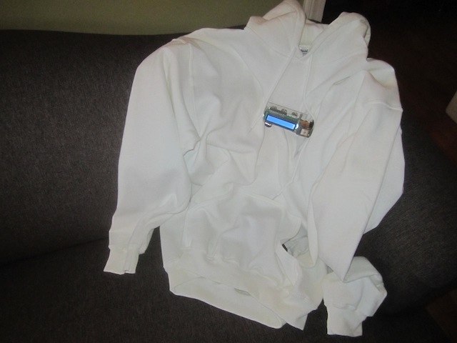
This was my first wearable project. Most wearables use conductive thread with light weight components, attaching a big heavy LCD and backpack to a shirt is not ideal. The big pocket on the hoodie made a good place to store the micro controller, MicroSD breakout and 9V battery. I decided that the GPS receiver should be mounted up with the LCD for good reception. Since the LCD and GPS are both serial devices they are connected to the micro with only two wires, the RX of the LCD and TX of the GPS. Add 5V and ground for four wires total.

USB cables have four wires and make a nice neat connection between the pocket and mounted components.
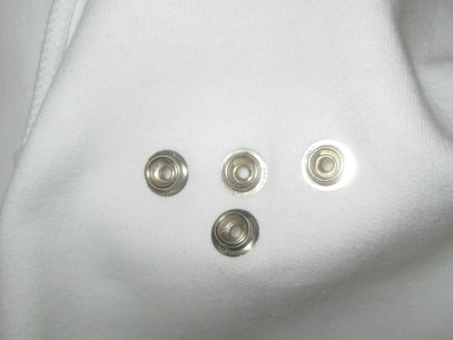
The GPS is on a small piece of perfboard which, along with the LCD, is mounted to a piece of Lexan by standoffs. I attached snap sockets to the hoodie with a snap tool and glued the corresponding snap caps to the Lexan. The LCD and GPS assembly can easily be remove to wash the shirt.
I wanted to pass the USB cable through the shirt near the LCD and into the pocket through the back. This presented a problem, since I didn’t have a clue how to do it. My mother-in-law came to the rescue, making button holes to pass the cable through.
Laughing in my Hoodie
The Hoodie Hoodie works well as a prototype of a smart wearable. It’s not the most practical shirt due to the size of the LCD. Tiny LCD screens are becoming popular in wrist watch sized devices and monitors worn on the body. To make something like the Hoodie Hoodie practical there will have to be larger, flexible LCD screens available. When that becomes a reality I think that decorative smart clothing will be ubiquitous.