You are hereHome / Arduino Projects / Project Page: Wireless Bike Turn Signal
Project Page: Wireless Bike Turn Signal
The Wired Bicycle
Electronics for bicycles are starting to proliferate. From multi-function computers to GPS navigation there are a growing number of handlebar mounted devices.
One of the difficulties of mounting rider-controlled electronics for the rear of a bike is figuring out how to run wires across the length of the bike. I built this project to determine the viability of using wireless technology on a bike.
Droid Does Signal
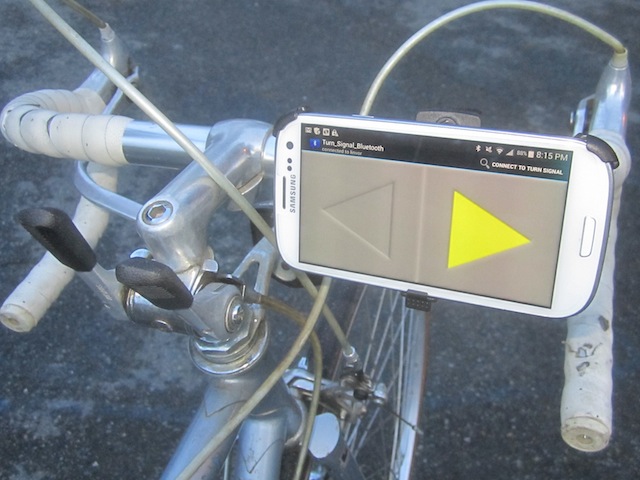 The controller is a Samsung Galaxy SIII Android phone. It’s great having an Android device because I am free to write whatever app I want for it. Owners of iOS devices must pay Apple for the privilege of writing apps for the device they purchased. One of the demo apps Google provides with the SDK is a Bluetooth chat program. I was able to modify their code to make my turn signal app.
Finding Proper Lenses
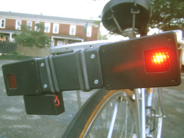 The turn signal is made from three project enclosures glued together. I wanted the two signals to have enough separation for distinguishing between a left or right signal. All the enclosures I found that were wide enough were too tall for my liking. The middle enclosure holds the electronics and the other two contain only the flashing LED.
From the beginning I knew the signals would look the best if authentic turn signal lenses were in front of the LEDs. Lens scraps were not terribly difficult to find by keeping an eye on the side of the road wherever I walked.
My first find was a nice piece of yellow lens spotted while waiting to cross the street to my office. I soon realized that this would not work for my purpose because of the way that it bent the light. A lens is made to work in a specific curved enclosure, so pulling out scraps does not always work.
 What proved to be the mother lode was a good sized piece of red lens I found in the gutter near campus after teaching a class at the university. The sidelong looks from nearby undergraduates who saw me scooping lens pieces off the street was a bit humiliating, but I was soon over it.
Blinker Electonics
On the turn signal side Bluetooth communication is handled by an inexpensive unit purchased from eBay. The Bluetooth feeds serial commands to an Arduino pro mini.
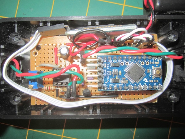 The LEDs are flashed by a 555. Transistors connected to the micro pins act as switches. The flashing speed is controlled by a trimpot.
The serial commands from Android are really simple. The chracter ‘l’ means turn on the left flasher, ‘r’ is for the right flasher and ‘s’ means stop flashing. The Android code always sends ‘s’ before ‘l’ or ‘r’ in case the rider pressed a turn signal while the other was on. There is no interface for a hazard flasher but it could easily be added, the controller would simply send ‘l’ followed by ‘r’. Sending ‘s’ would stop both signals.
The Ting Thing
I probably wouldn't even own a cell phone if not for finding Ting. They only charge $6 / month plus usage with no contract and are a great company. For someone like me who does not use many minutes, data or texts it works out great. I have a phone and can write Android apps whenever I want.
If you think that Ting is right for you please use my referral link when signing up for service. You will save $25 off Ting service or get $25 off a cell phone.