You are hereHome / Arduino Projects / Project Page: LED Matrix Sign
Project Page: LED Matrix Sign
Discovering MAX
It began when I bought an 8x8 LED matrix to experiment with. The first thing I noticed about the matrix was that the pins do not plug into a breadboard. This is how I learned about the special machine header pins meant to work with the types of pins on the matrix.
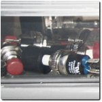
My next lesson was that powering and controlling 64 LEDs with nothing but Arduino pins is difficult or impossible. This is how I learned about the MAX7219 chip. Once one of these chips is wired up it is simple to control the matrix.
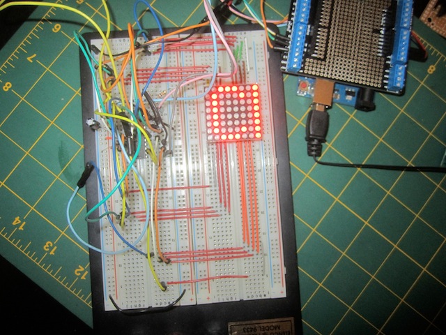 I went through the exercise of connecting the matrix and MAX7219 on a breadboard and realized that it requires about a mile of hookup wire. This is how I leaned about custom PCBs that pair an 8x8 LED matrix with a MAX7219 and are readily available on Ebay.
Arranging PCBs
I bought two of those rigs and built a scrolling display on a breadboard. Pleased with the results, I doubled the size. Another great thing about the MAX7219 is that they can be chained together to create large displays.
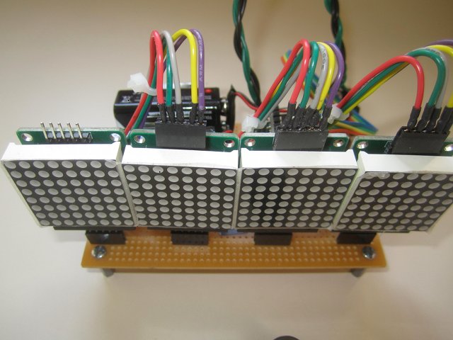 The MAX7219 is controlled by SPI, so only three Arduino pins are needed for the entire sign. The boards have five male header pins on the bottom for the three control lines plus VCC and ground. Those pins are echoed on the top of the board except for one of the pins. On the bottom this pin is labeled DIN and the corresponding pin on the top is DOUT. To chain boards together DIN of the first is connected to an Arduino pin, its DOUT runs to the DIN of the next board and so on.
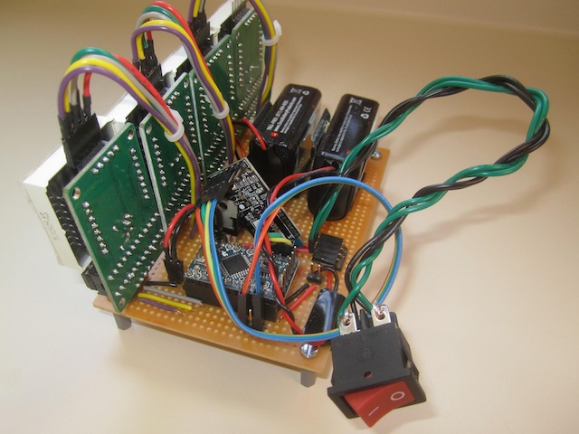 When I built a circuit board to hold the sign the pin arrangement of the boards made things a bit easier. Four sections of female header pins soldered to the proto board hold the LED boards. Instead of having to run wires all around the proto board I only needed to solder five wires next to the female headers and connect them to the top of the next board with a strip of female header pins.
The sign is controlled by a 5V Arduino Pro Mini and powered by two 9 volt batteries. The MAX7219 is a 5V chip so I added a voltage regulator to the mix. I had a nice DPST switch that powers both circuits with the throw of one rocker.
Messages Over the Air
The original plan was to hook up the sign to a computer and send it a message via the serial port every time I wanted to display something but I remembered that I had a BLE module that was not being used and decided to integrate it into the sign. An Android app that I had written for another project sends text over the serial port so I was good to go except for the limitation of BLE of only sending 20 bytes at a time.
In order to send longer messages to the sign I decided on tilde as an end of transmission character. The Android program was modified to send strings in chunks and append a tilde to the final one. On the Arduino side, data from the serial port is buffered until a tilde is read and then sent to the sign.
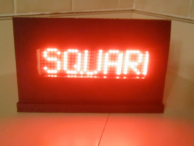 As a finishing touch I used my Dremel to cut a window out of a piece of plywood, glued it to a base and painted it black. It seems like a long journey from trying to use a lone matrix to wiring up a MAX7219 to building a sign, it was a good learning experience.